Unlocking Electronics: Understanding Electronic Symbols
Ever looked at an electronic circuit diagram and felt overwhelmed by a cryptic collection of shapes and lines? You're not alone. These seemingly complex figures are the fundamental building blocks of electronic communication – electronic symbols. They represent the various components within a circuit, allowing engineers and hobbyists alike to design, analyze, and troubleshoot electronic systems. Understanding these symbols is crucial for anyone venturing into the fascinating world of electronics.
Electronic symbols are a standardized visual language used globally to represent electronic components in schematic diagrams. This standardized representation ensures clear communication and understanding among electronics professionals, regardless of their native language or background. From simple resistors and capacitors to complex microcontrollers and integrated circuits, each component has its unique symbol. These symbols are essential for creating and interpreting circuit diagrams, making them the cornerstone of electronic design and analysis.
The history of electronic symbols dates back to the early days of electrical engineering. As circuits became more complex, the need for a simplified and standardized representation became increasingly apparent. Over time, various organizations, including the International Electrotechnical Commission (IEC) and the Institute of Electrical and Electronics Engineers (IEEE), have played a crucial role in establishing and maintaining these standards. The evolution of electronic symbols reflects the continuous advancement of electronics technology, from the simple symbols of early vacuum tubes to the intricate representations of modern integrated circuits.
The importance of standardized electronic symbols cannot be overstated. They provide a concise and universally understood way to represent complex electronic systems. This allows engineers and technicians from different parts of the world to collaborate on projects without ambiguity. Imagine trying to build a complex circuit without a standardized set of symbols – it would be like trying to build a house without blueprints. Electronic symbols are the blueprints of the electronic world.
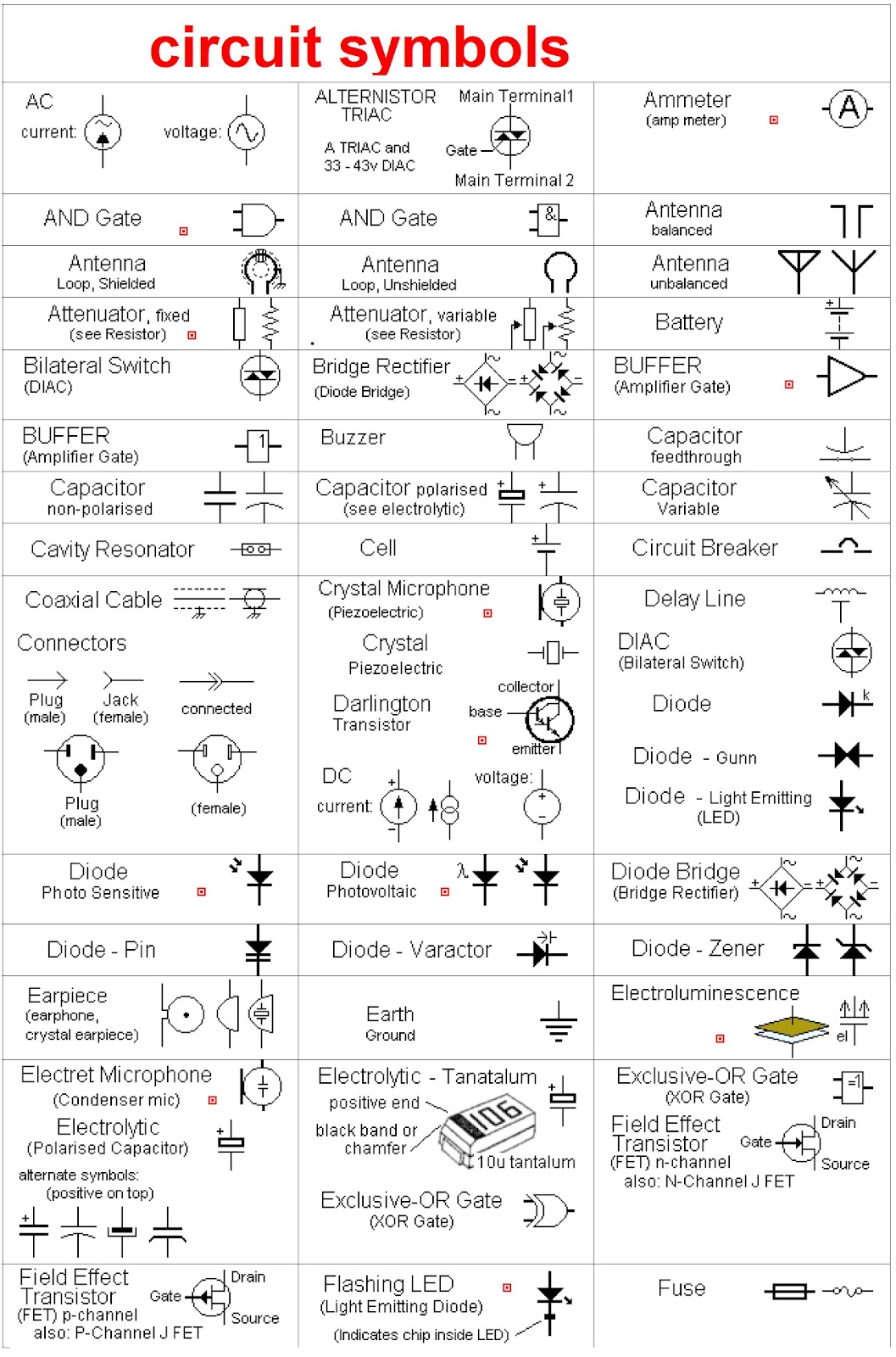
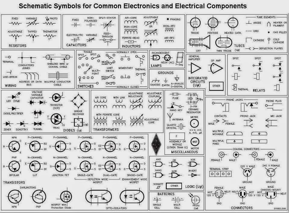
One of the main challenges related to electronic symbols is the sheer number of them. With the constant advancement in electronic technology, new components and their corresponding symbols are continuously being introduced. Keeping up with these additions can be demanding, especially for beginners. However, various resources, such as online databases and reference books, offer comprehensive libraries of electronic symbols, providing valuable support to learners and professionals alike.
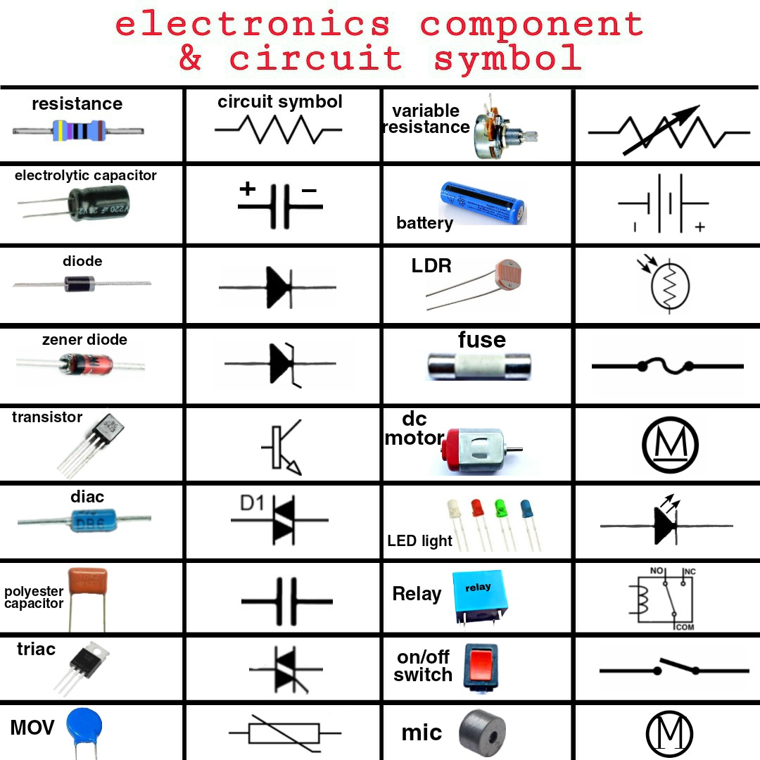
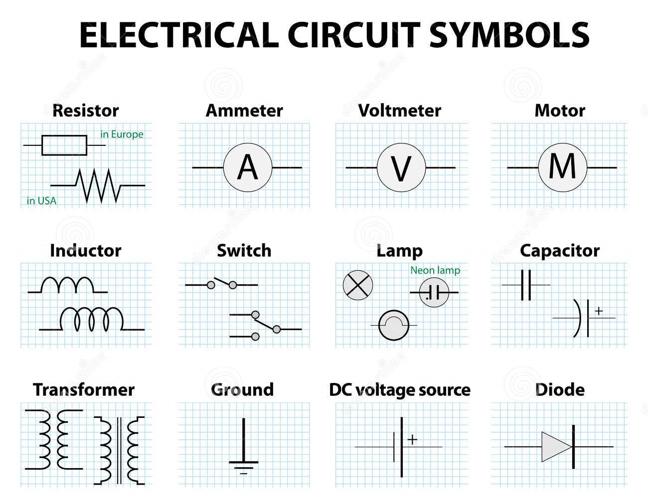
Understanding resistor symbols, capacitor symbols, inductor symbols, diode symbols, and transistor symbols is foundational to reading and interpreting electronic schematics. For instance, a resistor symbol, represented by a zig-zag line, signifies a component that restricts current flow. A capacitor symbol, depicted by two parallel lines, represents a component that stores electrical energy. Similarly, other basic component symbols have their unique representations and functions.
The benefits of using standardized electronic symbols are manifold. First, they promote clear and concise communication among electronics professionals. Second, they simplify the process of designing and analyzing complex electronic circuits. Third, they facilitate troubleshooting and repair of electronic equipment.
One successful implementation of electronic symbols is in the design of printed circuit boards (PCBs). PCB design software utilizes these symbols to create layouts for electronic circuits. This allows engineers to visualize and optimize the placement of components on a board, ensuring efficient performance and minimizing interference.
Advantages and Disadvantages of Standardized Electronic Symbols
| Advantages | Disadvantages |
|---|---|
| Clear and concise communication | Requires learning and memorization of many symbols |
| Simplified circuit design and analysis | New symbols are constantly being introduced |
| Facilitates troubleshooting and repair | Can be overwhelming for beginners |
Best practices for using electronic symbols include using the correct symbol for each component, maintaining consistency in symbol orientation, and clearly labeling all symbols. These practices contribute to creating easily readable and understandable circuit diagrams.
Real-world examples of electronic symbol usage include circuit diagrams for smartphones, televisions, computers, and automobiles. Every electronic device utilizes circuit diagrams composed of these symbols, highlighting their ubiquitous application.
Challenges in learning electronic symbols can be overcome by utilizing online resources, practicing reading and interpreting circuit diagrams, and building simple circuits to solidify understanding.
Frequently asked questions about electronic symbols often revolve around identifying specific symbols, understanding their functions, and finding resources for learning more about them.
Tips for mastering electronic symbols include focusing on the most commonly used symbols first, using flashcards or online quizzes for memorization, and regularly practicing reading and interpreting circuit diagrams.
In conclusion, electronic symbols are the essential language of electronics. Understanding these symbols opens up a world of possibilities in designing, analyzing, and troubleshooting electronic systems. From their rich history and development to their crucial role in modern electronics, mastering these symbols empowers you to navigate the complexities of electronic circuits with confidence. The benefits of clear communication, simplified design, and efficient troubleshooting afforded by electronic symbols are invaluable to anyone involved in the field of electronics. By embracing these symbols and utilizing available resources, you can unlock your potential in the exciting world of electronics. Take the time to learn these symbols, practice using them, and you will find yourself well-equipped to navigate the dynamic and ever-evolving landscape of electronic technology.
The impact of visual representation exploring the world of fotos de hombres guapos
Craving a crunchwrap supreme your guide to taco bell in portage wi
Decoding the trailer ball nut your hitch to hauling power


.jpg)


