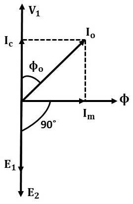
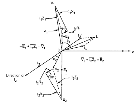
Unlock Transformer Secrets: Mastering Phasor Diagrams
Ever wonder how those massive metal boxes called transformers manage to juggle electricity with such finesse? The secret lies in understanding their inner workings, and phasor diagrams are the key to unlocking this knowledge. These diagrams are not just squiggly lines and arrows; they're a powerful visual language that reveals the dynamic relationship between voltages, currents, and magnetic fields within a transformer.
Creating a phasor diagram for a transformer isn't about memorizing complex formulas. It's about building a mental model of how these devices function. Imagine a transformer as a sophisticated gear system, where the primary and secondary windings are like interconnected cogs, transferring power smoothly. Phasor diagrams help visualize the timing and magnitude of these electrical "cogs" in action.
The concept of phasor diagrams stems from the early days of AC power systems, where engineers needed a way to represent sinusoidal quantities. These diagrams simplify the analysis of complex AC circuits by representing sinusoidal voltages and currents as rotating vectors, or "phasors." They're fundamental to understanding not only transformers but also other AC machinery and power system analysis.
One of the main issues when learning to draw these diagrams is understanding the phase relationships between the various voltages and currents. For example, in an ideal transformer, the primary and secondary voltages are in phase, while the currents are shifted by 180 degrees in a step-down configuration. Grasping these relationships is critical to accurately representing transformer behavior.
Getting comfortable with constructing these diagrams unlocks a deeper understanding of transformer operation. It's like being able to see the intricate dance of electrons within the windings, giving you the ability to predict and analyze transformer performance under different load conditions.
A phasor is a rotating vector that represents a sinusoidal quantity. Its length corresponds to the magnitude of the quantity, and its angle represents the phase. For instance, the primary voltage can be represented by a phasor V1, and the secondary voltage by V2.
One benefit of using phasor diagrams is visualizing voltage and current relationships. They allow you to see the phase shift between primary and secondary quantities, critical for understanding transformer operation.
Another advantage is simplifying complex calculations. By representing sinusoidal quantities as vectors, phasor diagrams simplify the analysis of AC circuits, making calculations more straightforward. For example, determining the voltage regulation of a transformer becomes a simple geometrical problem on the phasor diagram.
Thirdly, these diagrams help in troubleshooting. If a transformer isn't performing as expected, the phasor diagram can provide insights into the possible cause of the problem. For instance, an unusual phase shift might indicate a fault in the windings.
To draw a phasor diagram: 1. Choose a reference phasor. 2. Represent other quantities relative to the reference, considering their magnitudes and phase angles. 3. Label all phasors clearly.
Here's an example of a phasor diagram: consider a transformer which has V1=100 V at a phase angle 0. V2=120 V at a phase angle 30 degrees. You'll draw V1 as a horizontal line of length 100 units. V2 would be a line at 30 degrees from V1 of length 120 units.
Recommendations: Electrical Machinery by Fitzgerald is a good resource. Apps like Matlab/Simulink can also help simulate and visualize phasor diagrams.
Advantages and Disadvantages of Using Phasor Diagrams for Transformers
| Advantages | Disadvantages |
|---|---|
| Visualizes relationships between voltages and currents | Can be complex for non-ideal transformers |
| Simplifies calculations | Requires understanding of phasor concepts |
Five Best Practices: 1. Always start with a reference phasor. 2. Ensure accurate scaling for magnitudes. 3. Clearly label all phasors. 4. Consider the type of transformer (ideal, real) when drawing the diagram. 5. Use different colors for different quantities for clarity.
Real Examples: A step-up transformer with a turns ratio of 2:1, a step-down transformer with a turns ratio of 1:2, a three-phase transformer, an autotransformer, and a current transformer all have unique phasor diagrams reflecting their operation.
Challenges and Solutions: 1. Difficulty understanding phase relationships: Use a simulator to visualize. 2. Representing complex transformer models: Break down the model into simpler components. 3. Accurate scaling: Use graph paper or software. 4. Interpreting diagrams: Practice with different examples. 5. Connecting diagrams to real-world scenarios: Visit a substation or power plant.
FAQ: 1. What is a phasor? 2. Why are phasor diagrams used? 3. How do I choose a reference phasor? 4. What's the difference between a phasor diagram for an ideal and real transformer? 5. How does load affect the diagram? 6. Can I use software to draw these diagrams? 7. Where can I find more examples? 8. How do I interpret a phasor diagram?
Tips: Use a protractor for accurate angle measurement. Use software tools to automate the process. Start with simple examples before tackling complex ones. Practice drawing diagrams for different transformer configurations.
Mastering the art of drawing phasor diagrams for transformers is like gaining x-ray vision into the electrical world. It allows you to see beyond the metal casing and understand the dynamic interplay of voltages and currents within. This understanding is not only intellectually satisfying but also practically valuable for engineers, technicians, and anyone working with these essential devices. By visualizing these relationships, we can design, operate, and troubleshoot transformers more effectively, ensuring the reliable and efficient flow of electricity that powers our modern world. So, grab a pencil, a protractor, and perhaps a good textbook, and start unlocking the secrets of transformers. You’ll be amazed at the insights you gain and the power you unlock.
Unlocking safety mastering limit switch series wiring
The curious world of gacha life tiktok memes
Finding the right orthopedic care a comprehensive guide


