Decoding the Matrix: Your Guide to Electrical Symbols and Terminology
Ever stare at a circuit diagram and feel like you're deciphering hieroglyphics? You're not alone. Electrical symbols and terms can seem like a secret language, but they’re crucial for anyone working with electricity, from seasoned electricians to DIY enthusiasts. Understanding these symbols is like having a roadmap to the electrical world, allowing you to navigate circuits, troubleshoot problems, and even design your own electrical systems. So, let's ditch the confusion and illuminate the fascinating world of electrical symbology.
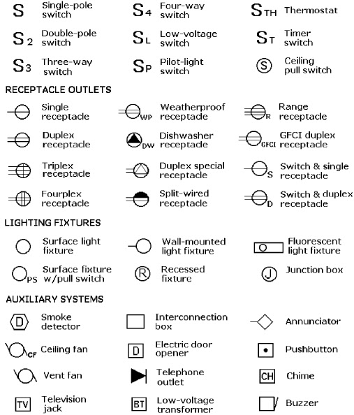
Electrical diagrams are the universal language of electricity. They provide a visual representation of electrical circuits, making it possible for anyone, anywhere, to understand how a system works. These diagrams rely heavily on standardized electrical symbols, representing various components like resistors, capacitors, and switches. Without a grasp of these graphical representations, navigating the electrical landscape would be like trying to read a book in a language you don't understand. It’s the foundation upon which safe and effective electrical work is built.
The history of electrical symbols is intertwined with the development of electricity itself. As scientists and engineers experimented with electrical phenomena, the need for a common visual language arose. Early diagrams were often crude, but they laid the groundwork for the standardized symbols we use today. Organizations like the International Electrotechnical Commission (IEC) and the Institute of Electrical and Electronics Engineers (IEEE) have played a critical role in standardizing electrical symbol terminology, ensuring clarity and consistency across the globe.
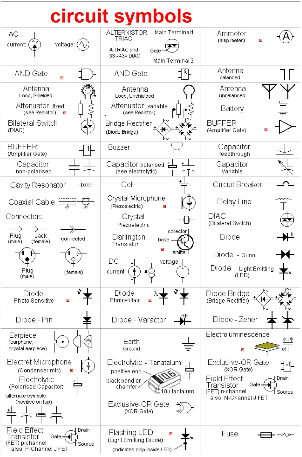
These symbols are not just arbitrary squiggles; they are carefully designed to convey information efficiently. For example, the symbol for a resistor resembles a zigzag line, visually representing the resistance to current flow. Similarly, the symbol for a capacitor, two parallel lines, reflects its ability to store electrical charge. These visual cues make it easier to understand the function of each component within a circuit. Imagine trying to describe a complex circuit using only words; it would be a nightmare! Electrical symbols simplify complex systems, making them accessible and manageable.
The importance of understanding electrical symbol definitions cannot be overstated. Misinterpreting a symbol could lead to dangerous wiring errors, equipment damage, or even injury. Imagine mistaking a ground symbol for a live wire – the consequences could be disastrous. Therefore, accurate interpretation of electrical symbols and their associated terminology is paramount for safety and proper functionality in any electrical system.
A resistor's symbol is a zigzag line, representing its function of resisting current flow. A capacitor's symbol, two parallel lines, indicates its charge storage ability. A switch is represented by a line breaking another line, visualizing its on/off function.
Benefits of understanding electrical symbols and terms include: 1) Improved communication between electrical professionals, 2) Enhanced safety through accurate circuit interpretation, and 3) Easier troubleshooting and circuit analysis.
Creating an electrical diagram involves identifying components, selecting corresponding symbols, and connecting them logically to represent the circuit's flow.
Recommendations: Explore online resources like All About Circuits, consult electrical engineering textbooks, and utilize mobile apps like Electrical Calculations.
Advantages and Disadvantages of Standardized Electrical Symbols
| Advantages | Disadvantages |
|---|---|
| Universal understanding | Requires initial learning |
| Simplified communication | Can be complex for large systems |
Best practices include using standardized symbols, labeling components clearly, and maintaining neatness in diagrams.
Real-world examples include house wiring diagrams, automotive electrical systems, and industrial control panels.
Challenges like evolving standards and software compatibility can be addressed through continuous learning and software updates.
FAQ: What is a resistor? How does a capacitor work? What is the symbol for a diode? What is AC/DC? What is grounding? What is a transformer? What is an inductor? What are the different types of switches?
(Provide general answers to each)Tips: Utilize online symbol libraries and practice drawing circuits regularly.
In conclusion, understanding electrical symbols and terms is paramount for anyone working with electricity. From basic home wiring to complex industrial systems, these visual representations and their associated language provide the foundation for clear communication, accurate design, and safe operation. Mastering these symbols empowers individuals to confidently navigate the electrical world, troubleshoot problems, and contribute to the ongoing development of electrical technologies. So, embrace the challenge, delve into the world of electrical symbology, and unlock the power of electrical understanding. Start learning today, and you'll be surprised at how quickly you can decipher the "matrix" of electrical diagrams.
Glory road inside the us olympic track and field trials
Discovering chula vista living vista del mar court
Finding james moore unraveling obituaries in indiana


.jpg)
