Decoding the Language of Circuits Electronic Component Symbols
Imagine trying to build a complex structure like a skyscraper without blueprints. It would be chaotic and nearly impossible. Similarly, in the world of electronics, electronic component symbols serve as the essential blueprints for designing and understanding circuits. These graphical representations are the language of electronics, allowing engineers and hobbyists to communicate and collaborate effectively.
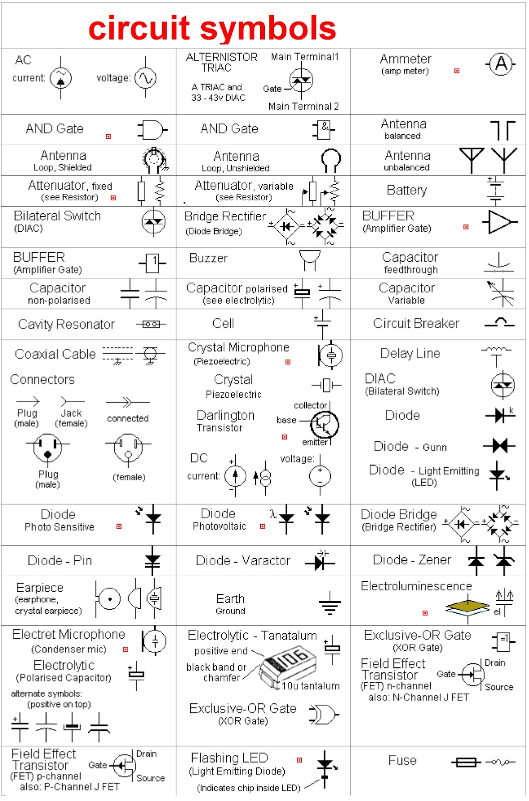
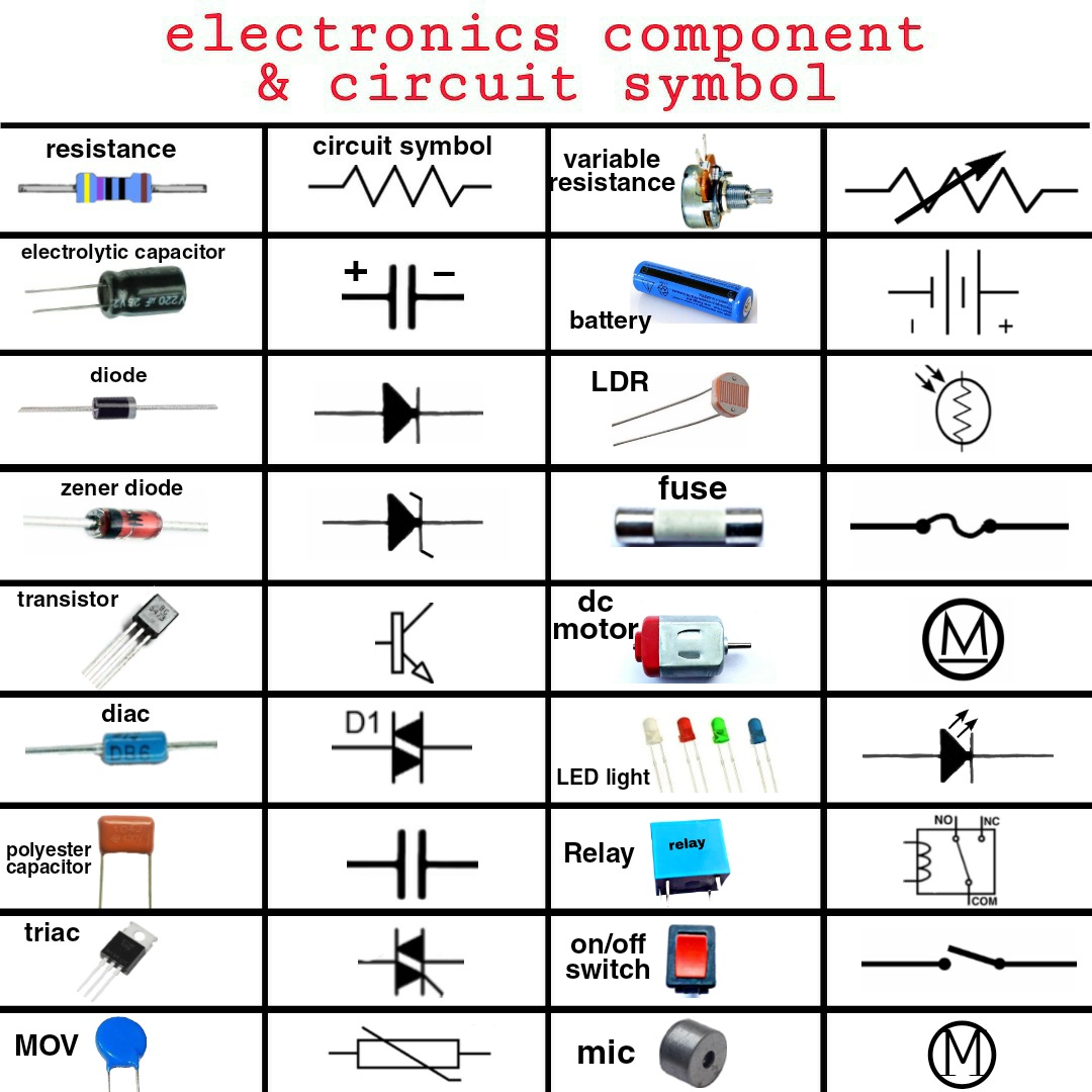
Electronic component symbols are standardized pictograms used to represent various electronic components in circuit diagrams. These symbols convey essential information about the component's function and characteristics, enabling clear and concise communication between designers, technicians, and enthusiasts. From simple resistors to complex integrated circuits, each component has a unique symbol that helps decipher its role within a circuit.
The need for a standardized system of electronic component symbols arose with the increasing complexity of electronic circuits. Early electronic diagrams were often messy and difficult to interpret, leading to confusion and errors. The standardization process evolved gradually, with various organizations contributing to the development of a universally accepted set of symbols.
These standardized representations are more than just convenient shorthand. They are fundamental to the design, analysis, and troubleshooting of electronic circuits. They facilitate communication across geographical boundaries and language barriers, enabling global collaboration in the field of electronics. Imagine trying to explain a complex circuit design using only words – it would be a daunting task. Electronic component symbols make this process significantly more efficient and accurate.
Understanding the meaning of these symbols is crucial for anyone working with electronics. Whether you are a seasoned engineer designing a new device or a beginner just starting to explore the world of circuits, knowing how to interpret these visual cues is essential for success. This knowledge empowers you to read circuit diagrams, understand how circuits function, and troubleshoot any potential issues.
Historically, electronic schematic symbols have evolved alongside the components they represent. Early symbols often resembled the physical appearance of the component. Over time, as circuits became more complex, the symbols became more abstract and standardized to improve clarity and consistency.
The importance of consistent electronic component symbols cannot be overstated. They are vital for efficient circuit design, troubleshooting, and communication. Without these standardized symbols, the electronics industry as we know it would be significantly hampered.
One of the main issues related to electronic component representation is maintaining consistency across different regions and industries. While international standards exist, variations can still occur. It is crucial for designers and technicians to be aware of these potential discrepancies to avoid misinterpretations.
A simple example is the resistor. Its symbol is a zigzag line, representing the resistance to current flow. A capacitor, which stores electrical charge, is represented by two parallel lines. These simple yet effective symbols clearly convey the components' functions within a circuit.
One benefit of standardized symbols is improved communication. They allow engineers worldwide to easily understand circuit diagrams, regardless of their native language. Another benefit is enhanced troubleshooting. By quickly identifying components within a circuit, technicians can more effectively diagnose and repair faults. Finally, these symbols streamline the design process, enabling engineers to create and modify circuits with greater efficiency.
A practical action plan for learning electronic component symbols involves starting with the basics. Familiarize yourself with the most common symbols, such as resistors, capacitors, and transistors. Then, gradually expand your knowledge by exploring more specialized components. Using online resources, textbooks, and practical circuit-building exercises can significantly aid in this learning process.
Advantages and Disadvantages of Standardized Electronic Component Symbols
| Advantages | Disadvantages |
|---|---|
| Improved communication | Potential variations in standards across regions |
| Enhanced troubleshooting | Need for ongoing learning to keep up with new symbols |
| Streamlined design process | Can become complex for highly specialized components |
Best practices for implementing standardized symbols include adhering to international standards, using clear and consistent labeling, and regularly reviewing and updating symbol libraries. This helps maintain accuracy and clarity in circuit diagrams.
Real-world examples of electronic component symbols can be found in any electronic device. From the simple circuit of a flashlight to the complex motherboard of a computer, these symbols are ubiquitous in the world of electronics.
One challenge in using electronic symbols is the sheer number of different components and their corresponding symbols. A solution is to utilize online resources and component libraries that provide comprehensive symbol databases.
Frequently asked questions about electronic component symbols often revolve around specific component representations, variations in standards, and resources for learning more about these essential symbols. Many online forums and educational websites offer answers to these common queries.
A helpful tip is to use flashcards or online quizzes to memorize electronic component symbols. This can make the learning process more interactive and engaging.
In conclusion, electronic component symbols are the cornerstone of electronic circuit design and understanding. Their standardized representation facilitates clear communication, efficient troubleshooting, and streamlined design processes across the globe. From simple resistors to complex integrated circuits, these symbols are the essential building blocks of the language of electronics. Understanding and utilizing these symbols effectively is crucial for anyone working with or learning about electronics. By embracing these visual cues, we unlock the power to design, analyze, and innovate in the fascinating world of electronics. Continue exploring the vast landscape of electronic components and their symbols – the possibilities are endless.
Cruising sydney your guide to finding the perfect rav4
Navigating the waters understanding marine insurance policies
Unveiling the power of ancestral bloodlines in light novels


