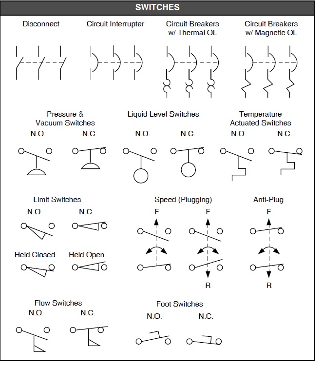
Decoding Level Switch Diagrams: A Deep Dive into Fluid Control
Ever wondered how machines "know" when a tank is full or empty? The answer often lies in a small but crucial component: the level switch. Understanding the graphical representation of these switches, commonly known as a level switch schematic symbol, or level indicator diagram, is essential for anyone working with fluid control systems. This deep dive will unlock the secrets of these symbols, exploring their history, significance, and practical applications in various industries.
Level switches are the unsung heroes of countless industrial processes, silently monitoring fluid levels and triggering actions based on pre-defined thresholds. From regulating the water level in your coffee maker to managing complex chemical reactions in a refinery, these devices ensure smooth and safe operations. Their representation in schematic diagrams, often simplified to essential elements, allows engineers to design, troubleshoot, and maintain these systems efficiently.
The evolution of level switch schematic symbols mirrors the advancements in control system technology. Early representations were often rudimentary, evolving from simple hand-drawn sketches to standardized symbols used across various engineering disciplines. This standardization, crucial for clear communication, ensures that engineers worldwide can interpret and work with these diagrams seamlessly.
The importance of accurately interpreting level switch diagrams cannot be overstated. Misinterpreting a level sensor symbol, such as a float switch schematic symbol, can lead to system malfunctions, costly downtime, and even safety hazards. A thorough understanding of these symbols is paramount for ensuring the reliable and efficient operation of fluid management systems.
Different types of level switches exist, each with unique operating principles and corresponding schematic symbols. A common type is the float switch, represented by a symbol depicting a float connected to a switch mechanism. Other types include capacitive, ultrasonic, and pressure-based level switches, each employing distinct sensing technologies and represented by specific symbols.
One key benefit of using standardized level switch schematic symbols is the ability to quickly visualize and understand complex systems. This visual representation simplifies troubleshooting and maintenance, allowing technicians to identify and address potential issues rapidly. Furthermore, using standard symbols promotes clear communication and collaboration among engineers, ensuring that everyone is on the same page.
Another advantage is enhanced safety. By providing a clear picture of the control system, level switch symbols enable operators to anticipate potential hazards and take preventative measures. Accurate diagrams are essential for implementing safety protocols and minimizing the risk of accidents.
Finally, the use of standardized symbols contributes to improved system design. By using a common language, engineers can optimize system performance, minimize complexity, and streamline the design process. This leads to more efficient and reliable fluid control systems.
When troubleshooting level switch systems, refer to the system's schematic diagram and verify the correct symbol interpretation. Check for common issues like wiring problems, faulty sensors, or incorrect calibration. For a float switch, inspect for obstructions or damage to the float mechanism.
Advantages and Disadvantages of Different Level Switch Types
A comprehensive comparison table will be added here in future revisions.
Implementing level switches effectively requires careful planning and execution. Best practices include selecting the appropriate switch type based on the application, ensuring proper installation and calibration, and implementing regular maintenance procedures.
Real-world examples of level switch applications abound. From monitoring fuel levels in aircraft to controlling water levels in wastewater treatment plants, these versatile devices play a critical role in countless industries.
Challenges related to level switch implementation often involve dealing with harsh environments, material compatibility issues, and ensuring accurate measurements in turbulent fluids. Solutions include using robust sensor materials, employing appropriate filtering techniques, and selecting specialized switch designs for challenging applications.
FAQs: What are the common types of level switches? How do they work? How do I choose the right level switch for my application? What are the common troubleshooting steps? What are the safety considerations? How do I interpret a level switch schematic symbol? What are the maintenance requirements? What are the latest advancements in level sensing technology?
Tips and tricks for working with level switches include ensuring proper grounding, using surge protection devices, and regularly inspecting wiring and connections.
In conclusion, understanding level switch schematic symbols is fundamental for anyone involved in designing, operating, or maintaining fluid control systems. These seemingly simple symbols represent sophisticated technology that plays a critical role in various industries, from manufacturing and processing to energy and environmental management. By mastering the intricacies of these diagrams, engineers and technicians can ensure the safe, efficient, and reliable operation of vital processes. Accurate interpretation of these symbols prevents costly errors, enhances safety, and optimizes system performance. Continuously educating yourself on new technologies and best practices related to level sensing will further enhance your skills and contribute to the ongoing development of this essential field. Embrace the power of these symbols to unlock a deeper understanding of fluid control and contribute to a more efficient and sustainable future.
The enduring legacy black american male singers and their impact
Meme uh ya va a llorar from viral sensation to cultural touchstone
Unlocking the quinceanera celebration your guide to a perfect 15th birthday


