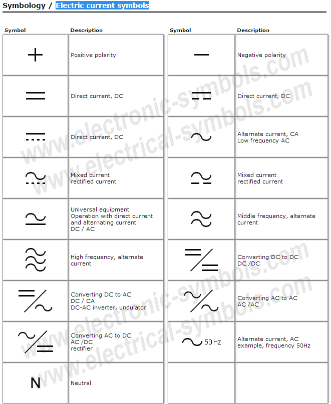
Decoding DC Circuitry: A Guide to DC Current Symbols
Ever stared at a circuit diagram and felt like you were deciphering an alien language? Those cryptic squiggles and lines aren't random doodles; they're the language of electronics, specifically the symbols representing direct current (DC) components. Understanding these DC current notations is crucial for anyone working with electronics, from hobbyists tinkering with LEDs to engineers designing complex power systems. This deep dive explores the captivating world of DC current symbolic representation, uncovering its history, importance, and practical applications.
The standardized graphical representations for DC current components didn't appear overnight. They evolved over time, driven by the need for a universal language to communicate circuit designs effectively. Imagine the chaos if every engineer used their own personal symbols! Standardization allows for clear communication and collaboration across the globe, preventing misinterpretations that could lead to faulty circuits or even dangerous situations.
The DC current symbol itself, often a straight line with an arrow indicating the direction of flow, is the foundation of circuit diagrams. This seemingly simple representation allows us to visualize the path of electrons in a circuit, making it easier to analyze and troubleshoot complex electrical systems. Without these standardized DC representations, designing and maintaining electronic devices would be a significantly more challenging task.
Beyond the basic DC current symbol, a whole universe of graphical representations exists for various components, such as resistors, capacitors, batteries, and switches. Each symbol conveys critical information about the component's function and characteristics, enabling engineers to design and analyze circuits with precision. These symbols are essential for understanding how different components interact within a circuit and how they contribute to the overall functionality of the system.
But what happens when these symbols are misused or misinterpreted? The consequences can range from minor inconveniences to catastrophic failures. A misplaced symbol on a circuit diagram could lead to a short circuit, damaging components or even causing a fire. This underscores the importance of accurately understanding and applying these symbols, especially in critical applications like aerospace or medical equipment.
The symbol for a DC voltage source, typically represented by a long and short parallel line, indicates the source of electrical potential difference that drives the current flow. A resistor, symbolized by a zigzag line, represents resistance to current flow. A capacitor, represented by two parallel lines, stores electrical charge. These are just a few examples of how symbols visually represent the function of DC circuit elements.
One key benefit of using symbols is clarity. Imagine trying to describe a complex circuit using only words – it would be a mess! Symbols provide a concise and visually intuitive way to represent circuits, making them easier to understand and analyze. Another advantage is universality. Regardless of language or technical background, engineers worldwide can understand a circuit diagram thanks to the standardized nature of DC current symbol depictions.
When creating a DC circuit diagram, start by sketching the circuit layout. Then, replace each component with its corresponding symbol. Ensure all connections are clearly marked, and the direction of current flow is indicated. Review your diagram carefully to ensure accuracy before building the physical circuit. A successful example of using DC current symbols is in the design of power distribution systems, where clear and accurate diagrams are crucial for safety and functionality.
Advantages and Disadvantages of Using Symbols for DC Current
| Advantages | Disadvantages |
|---|---|
| Clarity and Conciseness | Requires Learning the Symbols |
| Universal Understanding | Potential for Misinterpretation if Used Incorrectly |
Best Practices for Using DC Current Symbols: 1. Use standard symbols. 2. Clearly label all components. 3. Indicate the direction of current flow. 4. Keep diagrams clean and organized. 5. Double-check your work for accuracy.
FAQs: 1. What is the symbol for a DC power source? (A long and short parallel line). 2. What does a resistor symbol look like? (A zigzag line). And so on...
Tips and tricks: When drawing diagrams, use a ruler for neat lines. Clearly label all component values.
In conclusion, the seemingly simple symbols representing DC current and its related components play a vital role in the world of electronics. Their standardized nature allows for clear communication and collaboration, facilitating the design, analysis, and troubleshooting of complex electrical systems. Understanding and applying these symbols correctly is paramount for anyone working with electronics, ensuring the safety, functionality, and efficiency of the circuits they create. From the basic DC current symbol to the complex representations of various components, these notations are the foundation of our ability to harness the power of electricity. By mastering these symbols, we gain the power to design, build, and innovate in the ever-evolving field of electronics. So, the next time you encounter a circuit diagram, take a moment to appreciate the intricate language of symbols that allows us to communicate complex ideas with clarity and precision. This understanding empowers us to unlock the potential of electricity and shape the future of technology.
Unlocking spanish storytelling the power of the past
Holly anderson stony brook a comprehensive overview
Unlocking the powerhouse why you should care about your musculos en la espalda


