Deciphering Electrical Blueprints: A Guide to Electrical Layout Symbols
Imagine trying to assemble a complex piece of furniture without instructions. Frustrating, right? Electrical plans are the instruction manuals for wiring a building, and electrical layout symbols are the language they're written in. Without a firm grasp of these symbols, navigating the electrical landscape of a building becomes a confusing and potentially dangerous endeavor.
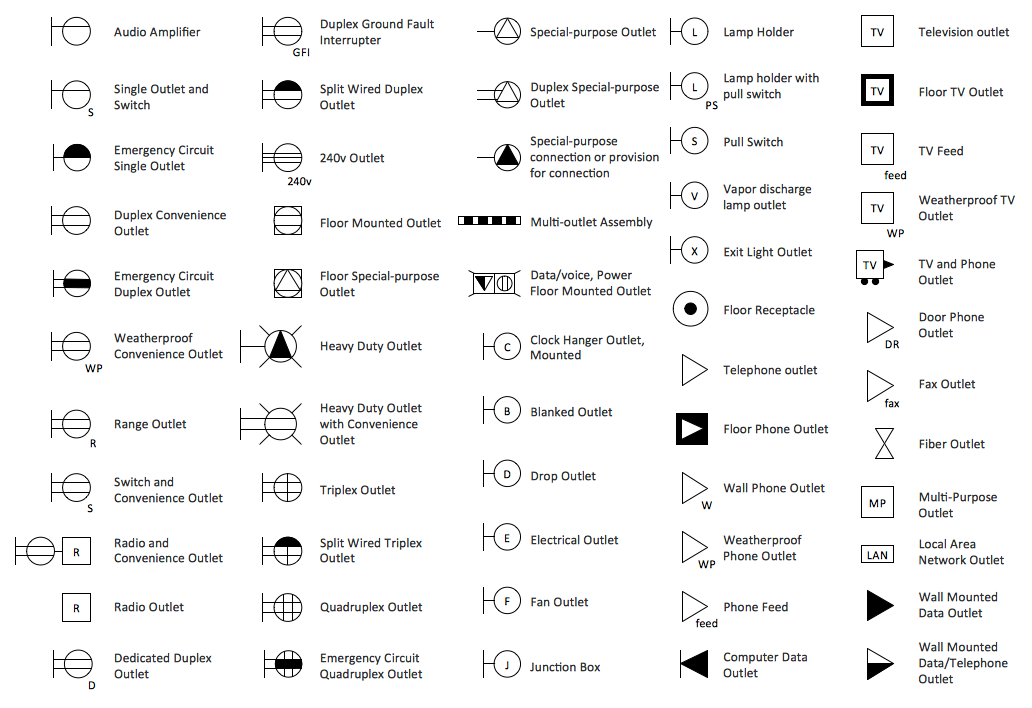
Electrical symbols on plans provide a visual representation of the electrical system within a structure. They depict everything from power outlets and light fixtures to complex wiring configurations and safety devices. This standardized language ensures that everyone involved in a project, from architects and engineers to electricians and contractors, can understand the intended electrical design.
The use of standardized electrical symbols emerged from the necessity for clear communication in the burgeoning field of electricity. As electrical systems became more intricate, the need for a universal visual language became apparent. Early diagrams might have been rudimentary, but over time, organizations like the IEEE (Institute of Electrical and Electronics Engineers) and IEC (International Electrotechnical Commission) helped establish standardized symbols, improving clarity and safety in electrical design.
These standardized electrical depictions are vital for several reasons. They ensure safety by clearly indicating the location of electrical components, allowing for proper installation and maintenance. They facilitate accurate cost estimations and material procurement by providing a detailed overview of the required electrical components. Furthermore, they are essential for troubleshooting and future modifications, as they provide a clear record of the as-built electrical system.
One of the primary issues surrounding electrical diagram interpretations is the potential for misinterpretation if the symbols are not understood or applied correctly. This can lead to costly errors during construction, safety hazards, and delays in project completion. Therefore, ensuring that everyone involved in a project understands these crucial markings is paramount.
For example, a simple circle with a cross inside represents a ceiling-mounted light fixture. A circle with a dot in the center indicates a wall-mounted light fixture. Understanding these subtle differences is critical for correctly installing the lighting system.
Utilizing standardized electrical representations offers several advantages. First, it enhances communication and collaboration among stakeholders, ensuring everyone is on the same page. Second, it improves safety by minimizing the risk of errors during installation and maintenance. Third, it increases efficiency by streamlining the construction process and reducing the likelihood of costly rework.
To ensure accuracy in your electrical plans, follow these best practices: 1. Use the latest version of the relevant electrical code standard. 2. Clearly label all symbols and include a legend on the plan. 3. Double-check your work for accuracy and consistency. 4. Seek expert advice when needed. 5. Maintain updated records of your electrical plans.
Advantages and Disadvantages of Standardized Electrical Symbols
| Advantages | Disadvantages |
|---|---|
| Clear Communication | Requires Training to Understand |
| Enhanced Safety | Potential for Misinterpretation if used Incorrectly |
| Improved Efficiency | Can be Complex for Large Projects |
Commonly encountered symbols include those for switches, receptacles, circuit breakers, and grounding points. Each symbol has a specific meaning, crucial for proper interpretation of the electrical layout.
Challenges in using electrical symbols can include keeping up with evolving standards and ensuring consistency across different software platforms. Solutions include subscribing to industry updates and utilizing software with built-in symbol libraries.
FAQ: 1. What is the symbol for a GFCI outlet? 2. How do I represent a three-way switch? 3. What is the standard symbol for a junction box? 4. How do I represent different wire gauges on a plan? 5. What is the symbol for a transformer? 6. How do I represent a light dimmer switch? 7. How do I show the connection of multiple light fixtures to a single switch? 8. What are the symbols for emergency lighting?
A tip for working with electrical drawings is to use color-coding to differentiate between different circuits or voltage levels. This enhances visual clarity and simplifies interpretation.
In conclusion, understanding and correctly applying electrical layout symbols is paramount for safe and efficient electrical system design and implementation. From ensuring clear communication among project stakeholders to minimizing the risk of errors and promoting streamlined construction, the benefits are undeniable. By following best practices, staying informed about evolving standards, and utilizing available resources, you can confidently navigate the world of electrical drawings and ensure the successful completion of your projects. Embrace the language of electrical symbols – it's the key to illuminating your projects with success. Take the time to familiarize yourself with the relevant standards and resources available, ensuring your electrical plans are clear, accurate, and contribute to a safe and functional electrical system.
Power on the go exploring portable jump starters from harbor freight
Btb savage navigating the impact of excessive motion
Finding juniper your guide to sourcing juniper plants and berries


